This is an old revision of the document!
Table of Contents
<texit info> author=Johnny Rieper, Bent Bisballe Nyeng and Kasper Sohn title=Marvin - The Balancing Robot. </texit>
Stikord
- Stadigt voksende klassediagram
- Styring
- Dreje (gammel / alternativ metode)
- Frem / Tilbage (gammel / alternativ metode)
- Stabilisering ved sinus
- Nye hjul. Stor friktion på gulvtæppe ved gamle hjul –> Motivation til at skifte til nye hjul (slicks)
- Gyro offset float/drift problemet
- Hjul amok løsningen
- Udret fejl jvf. vinkel
- Batteri korrektion (fejl på reference til A/D konverter, drift i denne pga batteri spænding)
- Lille spredning i gyro –> nulstil gyro
- Addering af konstant offset
- Gennemsnitsmålinger på gyro
- Vægtet midling af alle gyrolæsninger –> VIRKER!!!
Lab report 3 - Driving
Date: January 14nd 2009
Duration of activity: 8-16
Participants: Kasper, Bent and Johnny
Project Goal
Make robot able to drive a predefined pattern.
Plan
- Create a Motor Control class that can append extra power to the motors individually to control how the robot is behaving.
DC Motor Drives
motor.png_the_nxt_dc_motor
The Lego Mindstorm kit comes with a set of DC Motors and therefore we shall give a short introduction to the DC motor and the DC motor controller. This will hopefully add nicely to the presentation of the H-bridge and DC servo motors given in the lesson given in week 4 of the course. Let us begin with the DC motor.1)
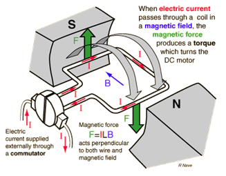
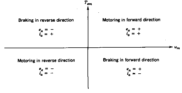
The DC motor is illustrated with a permanent magnet, but in many cases a electromagnet is used instead as it improves the performance of the DC servo motor. In a DC motor the rotor carries the electrical power as opposed to the AC motor, where the stator handles the power. The armature winding needs to be in the rotor of a DC motor to provide a rectification of the voltages and currents, which enables the motor to drive in all four quadrants. As we see on the illustration, the current is supplied externally through a commutator that rotates with the shaft and therefore carbon brushes are used to make contact between the commutator segments and supply terminals. The electric current is supplied through the brushed to the commutator where it passes through a magnetic field via the armature wire, hence the magnetic force produces a motor torque that turns the rotor. This is standard physics, but one very important detail about the physics of the DC motor is the energy of the system. When the motor is running, the system contains energy that originates from the inertia of the motor load, and therefore the motor supply must be able to handle this energy when the motor is stopped or when we request a change of direction. When the motor is breaking the kinetic energy from the motor load inertia is converted into electrical energy. This means that the motor will try to uphold the voltage - meaning that the DC motor is now working as a generator supplying our motor controller, but notice that the direction of the electrical current has changed. In order to operate the DC motor, the controller must therefore be able to handle four-quadrant operation.
Power Electronic Converter
We see that the four quadrant refers to the four combinations of voltage and current directions. As mentioned the motor is actually transferring energy back to the supply when breaking and this requires special attention when designing a motor controller. In order to control the DC motor a Power Electric Converter (PEC) that satisfies the following conditions is needed. 2)
- The converter must allow both output voltage and current to reverse in order to yield a four-quadrant operation.
- For accurate control of position, the average voltage output of the converter should vary linearly with its control input, independent of the load on the motor.
- The converter output should respond as quickly as possible to its control input, thus allowing the converter to be represented essentially by a constant gain without dead time in the overall servo drive system.
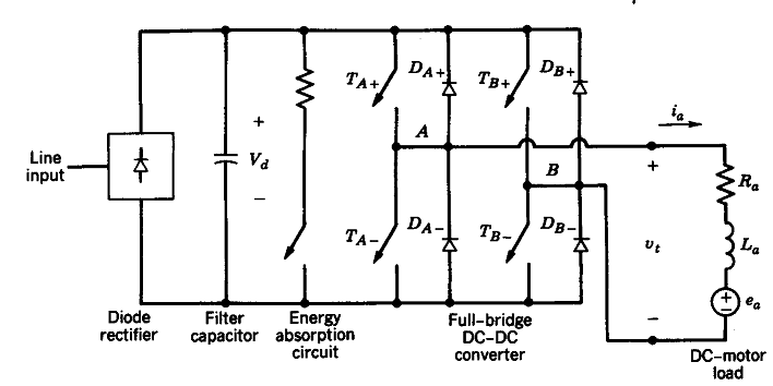
Further demands may be required, but these are essentials and adequate for our purpose. A linear power amplifier would be highly ineffective and therefore a switch mode dc-dc converter is used. A full bridge (H-bridge) converter is in fact capable of operating in all four quadrants and is illustrated on the following diagram.
Observe that it contains an energy absorption circuit in order to waste the kinetic energy from the motor load inertia by heating up a resistor. A more advanced solution would be to store the energy back to the battery, which we may assume in the NXT kit. Lastly we will demonstrate the four-quadrant behaviour of the full-bridge dc-dc converter.
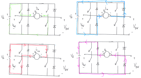
The top left illustration show forward motion, where two transistors are connected to guide the current forward through the DC motor - notice that the transistors are always connected pairwise. As we decide to change direction the transistors are disconnected in the blanking time, whereafter the other two transistors are connected. The rectifiers are mounted anti parallel and works as a valve for the aforementioned extra energy, that is either eliminated by the resister or fed back to the battery. This is illustrated on the top right, which indicates the forward breaking of the motor. Notice how the voltage and current directions are maintained in the breaking phase, since the motor is incapable of altering its direction instantaneous cf. our explanation regarding kinetic energy. The lower left illustrates the backward motion of the motor and finally lower right shows the backward breaking loop. We therefore see that the H-bridge is in fact capable of four quadrant motion, which is cleverly implemented using transistors and rectifiers. (The diagram is simplified, naturally). Fortunately the motor control is linear, which is a requirement in our control loop as it is a linear controller. However, the average voltage output does not vary linear with the control input voltage during the blanking time, which occurs when the motor direction changes. In our case this happens all the time to keep the robot in state of equilibrium and we may therefore expect some non linear behaviour from the motors.
Motor Encoder/Tacho Counter
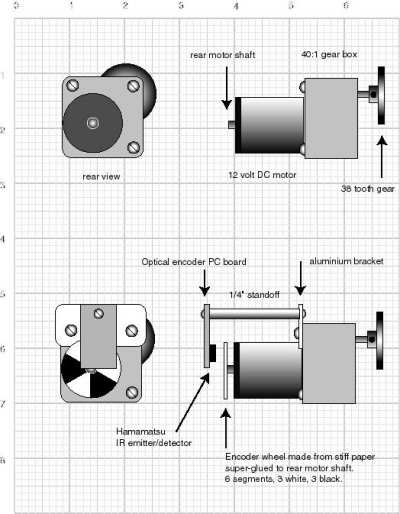
When designing the motors, wheels and drive train, it will almost always be important to have some sort of encoder feedback. In the Lejos framework there are methods to get readings from the tacho counters and these sensor readings have proven to be very useful when designing a balancing robot cf. the research literature in the introduction. In order to illustrate the concept of an encoder we use this simple set-up, which is explained in the excellent SRS Encoder article by David Anderson3). Imagine a DC motor without an encoder which is illustrated in the top of the figure. If we mount a circular image with a pattern determining our resolution, we can use a simple IR transceiver to get readings back to our micro controller or signal processing unit. In the Lego Mindstorm kit4) each motor has a built-in Rotation Sensor. This allows us to control the robot’s movements quite accurate. The Rotation Sensor measures motor rotations in degrees or full rotations [accuracy of +/- one degree]. One rotation is equal to 360 degrees, so if we set a motor to turn 180 degrees, its output shaft will make half a turn. This allows us to evaluate both the body angle and angle velocity of the balancing robot by means of simple differentiation, which is explained in one of the following sections.
Driving the Robot
Right/Left Steering
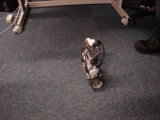
Now that the robot is balancing it ought to be simple to make it drive around. We expect the controller to maintain its balance even though we apply the necessary offset to the PWM in order to make it move. At first we added a small offset to one wheel and subtracted from the other, which caused the robot to drive in a circle. The robot actually seemed to be more robust when turning and we were able to reach a high speed when doing a circle “on the spot”. Maybe this has to do with the angular momentum that is being build up when turning on the spot - similar to the ice skater doing a pirouette. Also we reduce the slip in the motor by keeping the robot rotating. This can be seen on the following video
As you may have noticed on the video we did also change the tires. The tires in the original model had a course pattern and this caused it to get stuck on the carpet and so the robot did not behave equally on both carpets and slippery surfaces. By changing to a very flat tire we experienced more similar behaviours on different surfaces and this made the tuning of the parameters in the control loop a bit easier.
Forward/Backward Motion
The idea was then to make the robot move forward by adding a small offset on both wheels, but clearly this was not the right approach. Either the controller does not allow the robot to move, or it oscillates and crashes. The reason for this is actually quite clear if we recall our control loop.
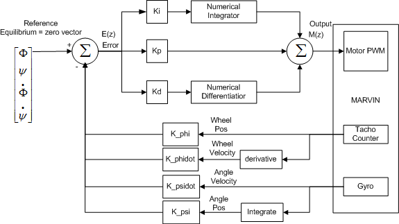
If we apply an offset to both wheels we are removing control from the controller and disturbing the calculated error. Either the control loop will overcome this disturbance by some minor oscillations or it will become unstable as we are really adding to the overshoot. This does not happen when we add a small offset to one wheel and subtract from the other since this does not affect the overall error signal. The natural place to control a closed loop control is of course the reference values, which are applied for each state. The reason that we did not use this approach immediately is probably that the reference values have been left unused as we want all the states to be zero in order for the robot to remain in equilibrium. If a small offset is added to the tilt angle (psi) the robot must remain in motion to stay balanced. Although the robot is capable of moving forward and backward it showed an undesired tendency to oscillate between forward and backward commands. As the contra steering used to turn the robot did seem to stabilize the robot, it seemed important to make the robot occupied in between commands by adding a small amount of contra steering. This will keep the motors busy and reduce the slip when the motors are changing from forward to backward motion simultaneously. We used a sine function to add a small offset to one wheel and subtract from the other as the sine function overall should make the robot remain in the same position - also we can quite easily alter the amount of offset. The real benefit from this is due to high amount of slip in the motors in the instant where they are not active. Before, this slip would point in the same direction, but with the small contra steering it actually points in separate directions, hence stabilizing the robot. Using this approach we are now able to control the robot as expected, thus we are able to make the robot drive a predefined pattern. It is important to mention that the robot still has a tendency to oscillate, which often requires the control loop to “interrupt” the desired motion causing the robot to move unexpected. Therefore the the robot is not able to drive according to the navigation class, but it is satisfactory in order to implement a behaviour control model. The goal of this lab session was to make Marvin capable of driving a predefined pattern, but we did not specify anything about the accuracy of its position or which type of pattern. We are currently satisfied with the progress and we find the result satisfactory with respect to the next lab session in which we shall implement the behaviour based control model.
MotorControl
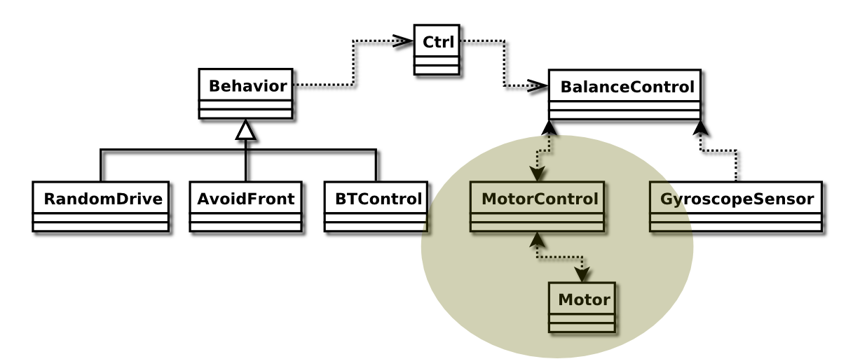 The MotorControl class handles the motors. It works as a control interface on top of the actual Motor ports, and ca report angle and angle velocity (using the TACHO counter) of both of them, as well as set the power and direction.
A small stabilizing algorithm is located at the top of the setPower(…) method. It makes sure that the gears of the motors are always tightened, to minimize the slack on direction change.
This is done by adding a small amount of power controlled by a sin function, which makes the robot wriggle a tiny bit when standing absolutely still (this is actually noticeable if whatched carefully).
The motor angle and angle velocity methods simply uses the average of the values from the actual motor ports.
The code for these things can be seen below:
class MotorControl
{
  private Motor leftMotor;
  private Motor rightMotor;

  .
  .
  .

  public void setPower(double leftPower, double rightPower)
  {
    sin_x += sin_speed;
    int pwl = (int)( leftPower + Math.sin(sin_x) * sin_amp );
    int pwr = (int)( rightPower - Math.sin(sin_x) * sin_amp );

    leftMotor.setSpeed(pwl);
    if(pwl < 0) {
      leftMotor.backward();
    } else if(pwl > 0) {
      leftMotor.forward();
    } else {
      leftMotor.stop();
    }

    rightMotor.setSpeed(pwr);
    if(pwr < 0) {
      rightMotor.backward();
    } else if(pwr > 0) {
      rightMotor.forward();
    } else {
      rightMotor.stop();
    }
  }

  public double getAngle()
  {
    return ((double)leftMotor.getTachoCount() + (double)rightMotor.getTachoCount()) / 2.0;
  }

  public double getAngleVelocity()
  {
    return ((double)leftMotor.getActualSpeed() + (double)rightMotor.getActualSpeed()) / 2.0;
  }
}
Ctrl
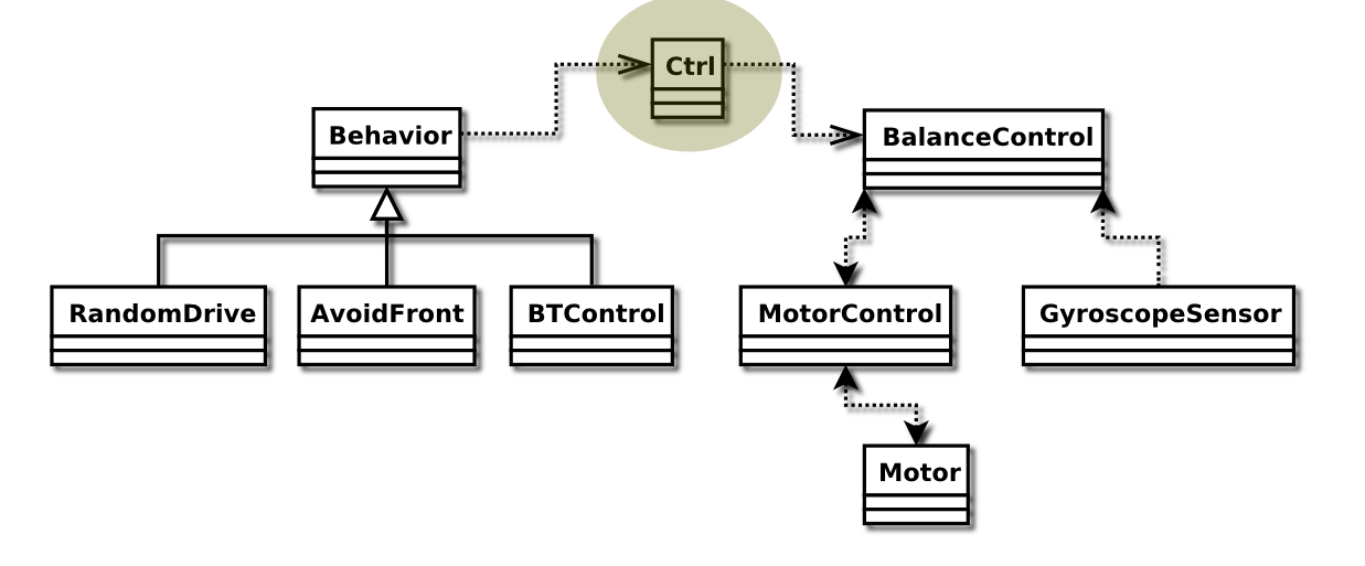 The Ctrl class is used to handle the control parameters of Marvin.
It is used for cross thread communication, and simply sets and gets a number of parameters through synchronized methods.
The parameters are left and right motor power offsets, and gyroscope tilt angle offset.
A way to make Marvin drive in a hardcoded path was to set these values directly in the Ctrl class, and use a counter to switch values after a predefined number of iterations (simply increment the counter upon each get call and switch when the value is high enough).
The code for the offsetLeft value can be seen below, the code for rightOffset and tiltOffset works similar.
class Ctrl {
  private double offsetLeft = 0.0;

  .
  .
  .

  public synchronized void setLeftMotorOffset(double offset)
  {
    this.offsetLeft = offset;
  }

  .
  .
  .

  public synchronized double leftMotorOffset()
  {
    return this.offsetLeft;
  }

  .
  .
  .
}
The full source code for these classes can be found in the files MotorControl.java and Ctrl.java in the Marvin code tarball 5)

