This is an old revision of the document!
Lab report 7
Date: October 31th 2008
Duration of activity: 8-13
Participants: Kasper, Bent and Johnny
Project Goal
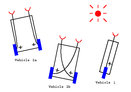
The project goal is to build and experiment with Braitenberg vehicles. The vehicles are shown here below.
Vehicle 1
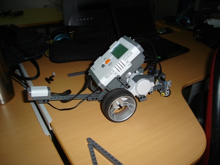
This vehicle is utilizes the simplest form of sensor→actuator activation. For this vehicle we shall replica a sensor/actuator system, which originally was connected through a wire-circuit in analog form, where the sensor signal presumably was amplified using transistor or operational amplifiers and fed to the motor. The vehicle behaviour is very simple. The more measured quantity from the sensor the more power is fed to the engine. In theory the sensor input is proportional to the sensor output, but in practice this relationship may not hold due to the sensor characteristic. Our objective is to implement this behavior in a digital form using the LEGO mindstorm NXT module in which we are able program this proportional relationship between sensor and actuator in a java based environment.
In our project a sound sensor is used instead of a light sensor. The source code for vehicle 1 is displayed below.
public class Vehicle1 {
  // Commands for the motors
  private final static int
    forward  = 1,
    backward = 2,
    stop     = 3,
    flt      = 4;

  private static MotorPort leftMotor = MotorPort.C;
  private static MotorPort rightMotor= MotorPort.B;

  public static void main(String [] args)  throws Exception {
    SoundSensor ss = new SoundSensor(SensorPort.S1);

    while (! Button.ESCAPE.isPressed()) {

      // Read value from light sensors
      int val = ss.readValue();

      LCD.drawInt(val, 0, 3);

      leftMotor.controlMotor(val, forward);
      rightMotor.controlMotor(val, forward);

      Thread.sleep(200);
      LCD.clear();
    }

    leftMotor.controlMotor(0, stop);
    rightMotor.controlMotor(0, stop);
  }
}
Observed behaviour
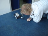
The first testrun indicated that the sensor was to close to the motors as the sensor readings were 93 (interval going from 0-100) when the motors were running. Therefore the sound sensor was placed further away from the vehicle. The problem was solved by simply placing the sound sensor 20cm. in front of the vehicle. The next testrun proved the expected behaviour for vehicle 1. The soundsensor reacts well to whistle sounds and by making higher amplitudes in a nice whistled sine tone the vehicle moves faster as expected.
Vehicle 2
This vehicle will move towards the light source. There are two light sensors placed in front of the vehicle seperated by approximately 10cm. The sensor that is nearest to the source will provide most power to the connected motor and thereby turning the car towards the light. The original analog circuit will correspond to a bang-bang controller in the digital form. The source code for vehicle 2 is displayed below.
Observed behaviour
The first testrun indicated that


