Table of Contents
Lab rapport 4
Date: September 26th 2008
Duration of activity: 8-12.30
Participants: Kasper, Bent and Johnny
The Purpose of this exercise is too make a balancing robot, using the NXT.
Experiments with the LEGO sejway, legway.
Building the legway
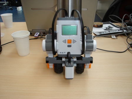
First we set out to build a robot with two wheels, following the build instructions on http://www.philohome.com/nxtway/nxtway.htm
Iteration towards The Balancing Marvin
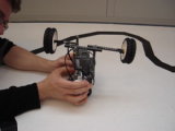
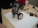
We first tried to use a boom to make Marvin balance, but it seemed that the effect were unnoticable. We achived the best results by applying larger wheels (as in larger diameter).
We also discovered that having an even coloured surface improved the performance. The value collected from the light sensor fluctuated greatly with the surrounding lights and to eliminate this, we used a tube around the lightsensor. This proved to be the tipping point in the mecanichs.
In the software we added a few lines of code. We added a range in error so if the error was negligible small, the error was set to zero to avoid oscilliations.
The last thing we added were another scale factor to reduce the power apllied to the motor. Again to avoid that Marvin were pushed too hard.
Programming
We used the code from Brian Bagnall, Maximum Lego NXTBuilding Robots with Java Brains, Chapter 11, 243 - 284. (http://www.variantpress.com/books/maximum-lego-nxt) as a basis for our own program.
The default values of the PID control parameters seemed to act too violently, so initially we tried changing the them and the scale factor:
// PID constants
final int KP = 28;
final int KI = 4;
final int KD = 33;
final int SCALE = 18;
We increased the D parameter to minimize the overshoot.
Tuning PID Parameters
The easiest way to tune the parameters would be if it was possible to do a simulation and see the phasemargin, but this is not available. Therefore we have observed the behaivor of Marvin and used the manual tuning methods listed on Wikipedia at http://en.wikipedia.org/wiki/PID_controller#Manual_tuning
A PID controller is based on three controllers placed in a cascade and they are very often shown in the Laplace domain, where the characteristics in terms of bandwith are more prominent. In our situation an in-depth analysis of the phase-margin is not available and therfore finetuning these controllers are made via the trial and error concept. The three figures from the wikipedia secton on PID controllers are very useful in order to get an intuitive understanding of the three controllers. These figures are shown here for convenience.
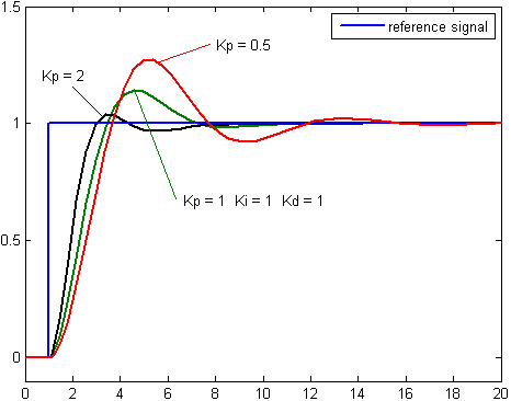
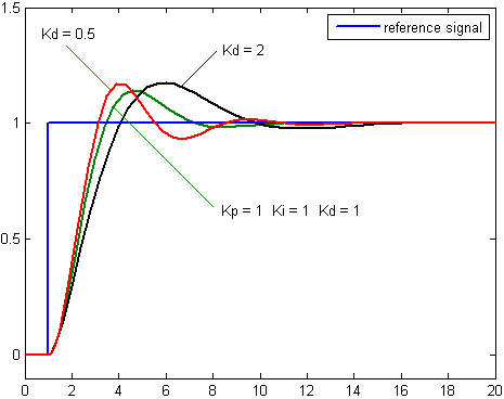
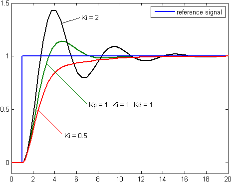
The above pictures are from http://en.wikipedia.org/wiki/PID_controller
By inspection we summarize the following. An increase in the proportional gain will create a larger overshoot, but reduce the steady state error and rise time. An increase in the integral controller also increase the overshoot, while eliminating the steady state error. (This is actually depending in how many poles we have in the system). If we increase the differential controller, we decrease the overshoot with no affect on the steady state error, but the bandwith of the system will be reduced. The deafault parameters in the program caused Marvin to oscillate to much, so based on the observed behavior of Marvin, we decided to increase the differential controller in proportion to the other controllers, thereby reducing the overshoot and hence the oscillation. In the following we have used the above guidelines and observations in an iteratively trial and error based estimation of the parameters.
Final code
Below are a listing of the final code:
    public void pidControl() {
	int normVal;
	int error;
	int deriv_error;
	int pid_val;
	int power;
	while (!Button.ESCAPE.isPressed()) {
	    normVal = ls.readNormalizedValue();

	    // Proportional Error:
	    error = normVal - offset;
	    if(Math.abs(error) < 3) error = 0;
	    // Adjust far and near light readings:
	    if (error < 0) error = (int)(error * 1.8F);

	    // Integral Error:
	    int_error = ((int_error + error) * 2)/3;

	    // Derivative Error:
	    deriv_error = error - prev_error;
	    prev_error = error;

	    pid_val = (int)(KP * error + KI * int_error + KD * deriv_error) / SCALE;

	    if (pid_val > 100)
		pid_val = 100;
	    if (pid_val < -100)
		pid_val = -100;

	    // Power derived from PID value:
	    power = Math.abs(pid_val);
	    power = 55 + (power * 45) / 100; // NORMALIZE POWER
	    power /= 3;
	    Motor.B.setPower(power);
	    Motor.C.setPower(power);

	    if (pid_val > 0) {
		Motor.B.forward();
		Motor.C.forward();
	    } else {
		Motor.B.backward();
		Motor.C.backward();
	    }
	}
    }
Conclusion
The main problem in balancing the robot seemed to be the fluctuations of the light sensor. We used three approaches to limit the fluctuations by changing the environment, the robotdesign and the software. The environment was changed by using clean white paper, which made the readings more reliable. Next, a tube was mounted around the sensor to make the sensor less susceptible to surrounding light fluctuations. Lastly we decided that an error of +/-3 would not would be overwrited to zero error. Some finetuning on these approaches may still be lacking. Another problem was the oscillations, which caused the robot wheels to turn too far in proportion to the error signal. We tried reducing this by increasing the proportional gain and reducing the overall gain. All in all the result is far better than the default program and the robot can actually balance for some time.
Future Improvements
In order to further reduce the oscillations we may read the tachometers on the motor. In this way we might be able to add these readings to the control loop and improve the control of the oscillaitons. There was one bug in the program we could not fix. Every ten seconds or so, the program got stuck for a second, which of course tripped the robot. We were unable to resolve this problem.

